Hybrid symbols
Read the guide
Give a 3D object a readable Top/Plan representation while keeping its modeled form for other views.
Decide what belongs in plan
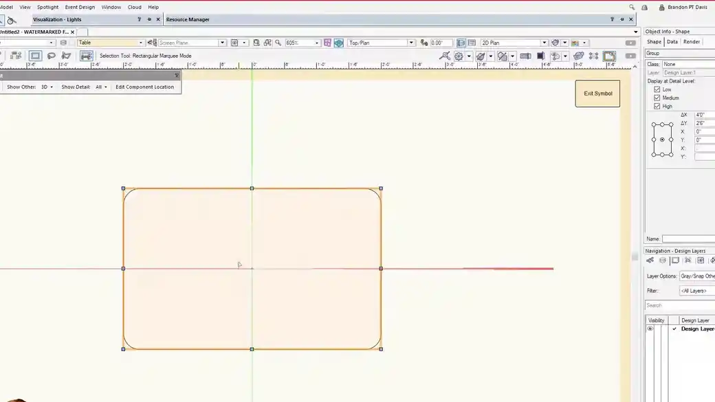
A modeled piece of furniture can create a lot of wireframe lines in Top/Plan. In the video, the table gets a 2D component that describes what someone needs to see in the ground plan.
Use the 3D object as a reference
Keep Show 3D on while drawing the 2D component so the drafted outline aligns with the model. After you exit the symbol, check both Top/Plan and an isometric view at the scale where the symbol will be used.
Work through it
- Create a symbol from the finished 3D table and choose a sensible insertion point, such as the center of the top in plan.
- Edit the symbol’s 2D component. Show the 3D component as a reference and trace only what readers need in Top/Plan, such as the footprint and any useful centerline.
- Exit the definition and test the same symbol instance in Top/Plan and an isometric view. Check the plan representation at the scale where it will appear on the sheet.
Quick reference
- 2D component
- The graphic to read in Top/Plan. Decide which edges are useful to someone reading the drawing.
- 3D component
- The modeled geometry used for object views and renders. Inspect it from an elevation after changing the plan graphic.
- Insertion point
- The common reference that keeps both components aligned when you place the symbol.
Put it into a scenic drawing
For a café table in a ground plan, use a clean outline and show hidden leg positions only if someone needs them to place the table. The elevations and renders can still use the modeled legs.
What to check
If the plan outline jumps when you switch views, compare its position to the 3D component inside the symbol definition. Also verify that you edited the Top 2D component.