From model to drawing
Read the guide
Use one scenic model to produce elevations, sections, and details that read as a coordinated drawing set.
Choose what each view needs to show
A front elevation needs clear linework. Hidden Line can clean up a wireframe view. Where modeled shadows help explain depth, the video pairs a rendered background with Hidden Line in the foreground. Compare the views at their printed scale.
Set a hierarchy for sections and details
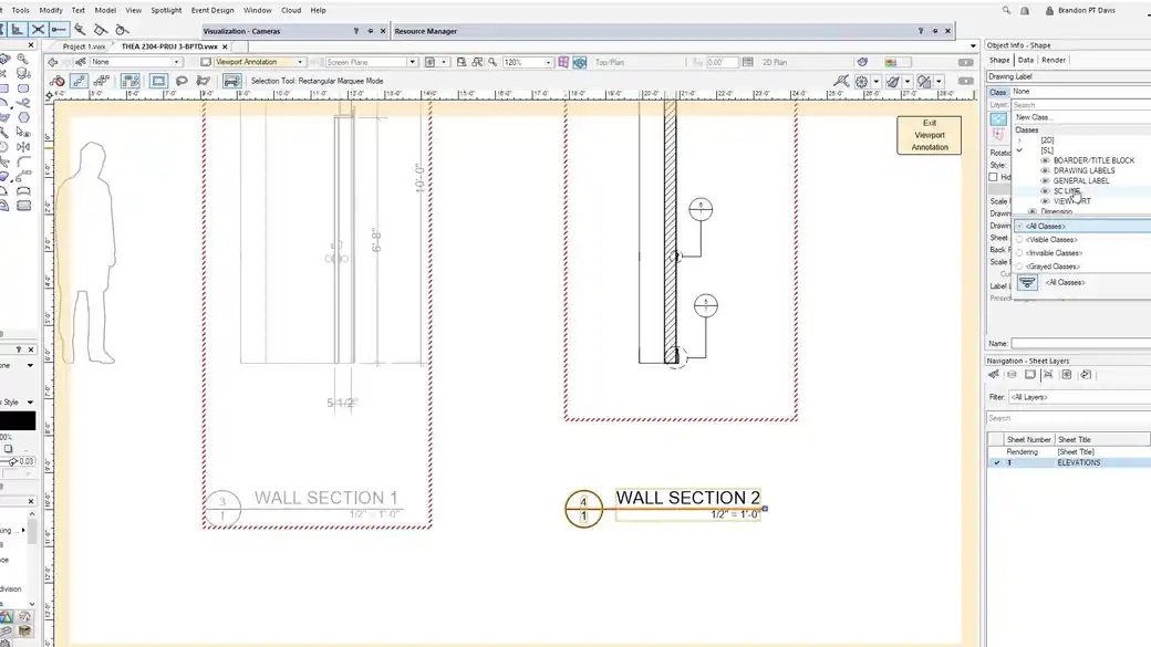
Make cut objects read clearly against the scenery beyond the cut. When the overall view cannot describe a detail, give it its own crop and scale. Before publishing, update viewports and check that every marker leads to the right drawing.
Work through it
- Choose a model view that answers a drawing question. Use a front elevation for opening locations and a section for relationships such as platform height, wall thickness, or framing depth.
- Create the viewport on a sheet, crop it, and choose a scale. Use Hidden Line where a clean elevation is enough. Try a rendered background with Hidden Line in front where shadows help describe the shape.
- Add reference markers and dimensions inside Annotations. Update your viewports after a model change and check that the section, elevation, and enlarged detail still agree.
Quick reference
- Elevation
- Shows the overall profile and positions of openings. Use a section when the assembly depth matters.
- Section
- Cuts through the model. Distinguish the cut material from the geometry seen beyond it.
- Detail viewport
- Uses a tighter crop and larger scale to make small construction or finish decisions legible.
Put it into a scenic drawing
Put the full wall elevation on the main scenic sheet. Cut a section through the door to show the depth of the assembly, then enlarge the baseboard where its profile is too small to read on the main elevation.
What to check
If the drawing still shows an older design, update the viewport and check its layer and class visibility before replacing the view.