Basics of 3D modeling
Read the guide
Start with a 2D outline, give it depth, and use simple volumes to shape a scenic object.
Check height in another view
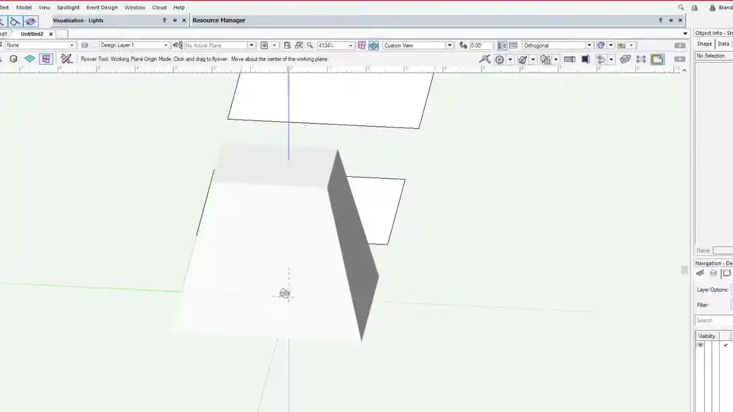
After you extrude a rectangle, change to an isometric or elevation view to see its depth. Extrusion height and Z position are separate. Change Z when the object needs to move above the layer plane without getting taller.
Work with volumes you can recognize
Use Add Solids to join pieces, Subtract Solids to cut an opening, and Intersect Solids to keep their shared volume. I start with shapes I can identify in plan and elevation. It makes it easier to find the source of a bad cut or an unexpected overlap.
Work through it
- Draw a closed 2D profile and extrude it. Switch to a side or isometric view to verify the new depth and where the object starts along Z.
- Make a second solid that overlaps the first. Try Add Solids for a continuous form or Subtract Solids for a cutout. In a subtraction, confirm which solid to keep before completing the command.
- Inspect the result from more than one view. Give the parts names you recognize if you expect to edit the operation later.
Quick reference
- Extrude
- Gives a flat profile constant depth. It works well for platforms, flats, and panel stock.
- Add Solids
- Joins overlapping volumes. Keep separate components if they still need to move or be edited separately.
- Subtract Solids
- Cuts the second volume from the first. Extend the cutting solid beyond a face for a through-opening.
Put it into a scenic drawing
Model a step as a rectangular extrusion. To make a cable notch, overlap it with a smaller block that extends through the full area of the cut. Compare the shape in plan and side elevation.
What to check
When a Boolean gives an unexpected shape, check that the two solids genuinely overlap in three dimensions. A profile that looks closed can still have a small gap that prevents it from making a solid.